DRAWN CUP NEEDLE CLUTCH
|
Drawn
cup needle clutch HF series and HFZ series |
|
The
drawn cup needle clutch HF, HFZ series is composed of thin wall punched
outer ring and plastic retainer. There is a clamping slope which holds
the needles tightly on the inradius surface of the alloy steel punched
out ring . the abrasion resistance and load capacity is greatly increased
after special heat treatment. Metal springs are fitted on the plastic
retainer which keeps the correct movement of the needles while the
needles are used as clamping unit at the same time. Through
fitting RTL drawn cup needle roller bearing HK, SCE series of the
same diameter on the two sides of drawn cup needle clutch, better
supporting rigidity and rotation characteristics are achieved. |
drawn cup needle clutch HF/HFZ |

|
Drawn
cup needle clutch and bearing assembly HFL series and HFlZ series |
|
Drawn cup needle clutch and bearing
assembly HFL, HFLZ series has a two-in-one supporting bearing which
can be a special space-saving support. The supporting bearings fitted
be the two sides of the needle clutch bear the radical load . The
support bearings are needles and the plastic retainer. |
Drawn cup needle clutch and bearing assembly HFL/
HFlZ |

|
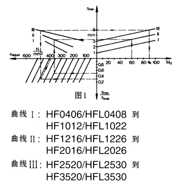
Torque
transmission capacity |
When the recommended assembling tolerances are adopted, the maximum transmitting torque is mainly decided by the
material, strength and wall thickness of the seat case and shaft. In a clutch, only enough wall thickness and appropriate material
strength can sustain the force resulted. Inertial force should be taken into account. For the equivalent caused by the torque and the
minimum wall thickness , please refer to Figure 1. The equivalent stress should be less than the stress permitted by the seat mat-
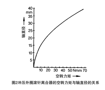
erial. For the relation between free torque and axle diameter , please refer toFigure 2.
|
Example: |
     A known: drawn cup needle clutch HF3020
     Load capacity: 90% of Md
     Present wall thickness: Sexis=16mm
     From Fig 1: minimum wall thickness Smin=4.8mm
     Equivalent stress бequiv=380N/mm2
     B; known: drawn cup needle clutch HF1416
     Permissive stress of seat casing бperm=300N/mm2
     Selective ratio of the seat casing wall thickness Smin/Sexis=0.5
     From Fig 1: minimum wall thickness Smin=3.2mm
     Permissive torque Md perm=60%Md
|
The switching frequency and
precision |
|
The
needle clutch has a very small torque due to its thin radical section.
Because each needle is supported by an independent spring, a constant
contacting is maintained among the slopes of shaft, needles and punched
outer ring, higher switching frequency and precision are allowed.
Beside the switching frequency, the switching precision is depended
on the selection of lubrication and combination. The elastic deformation
of the neighboring parts and driving force are transmitted through
the shaft or outer ring. The driving force is transmitted through
shaft when the frequency is high. |
|
|
Feature
inspection |
|
The tools used by the manufacturer in inspection
of drawn cup needle clutch are feeler gage and ring gage which are
in seat hole and shaft tolerance range N6/h5 upper limit and lower
limit. Meanwhile , the torque it sustains is approximately 0.15Md
perm. The feeler gage used is quenched steel ring with its aperture
precisely ground and the minimum wall thickness of 20mm. |
|
|
Operational
temperature and lubrication |
                        With good lubrication,RTL drawn cup needle clutch can be operated for  a long time under the temperature between
              -30℃-20℃. When the temperature is below -10℃or the speed is greater than 0.7 *nj, to ensure the normal functions of
              the bearings,  recommended lubricants should be selected. In most cases, there are enough lubricants. So the products
              are filled in advance the quality lithium based grease in compliance with the national  standards with the applicable
              temperature from -10℃to 70 ℃. Oil lubrication is recommended when the temperature exceeds 70℃.
|
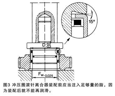
Mounting
tolerance |
|
When
mounting , the shaft and the seat hole with a chamfered angle of 15
degrees will help to get the best fitting condition. The mounting
method is shown in Fig 3. The needles and the thin wall punched outer
ring of the clutch will get the concentric configuration only after
being fitted into the seat. No other axle positioning is necessary.
The mounting tolerance is the same as that of the drawn cup needle
bearing. See table 1. The seat hole surface roughnes is Ra0.8 . |
|
|
Bearing seat material (rigid
bearing seat) |
Bearing seat hole tolerance |
Shaft tolerance range Without inner ring |
Inner ring |
|
Steel and cast iron |
N6(N7) |
h5(h6) |
k5(j6) |
|
Light metal |
R6(R7) |
               1)  for non rigid bearing seats, fitting tests are needed to determine the required common tolerance limit so that the operational gap can be achieved.
               2) The geometric precision of the cylinder shape of the bearing seat hole must fall into the half range of the value in IT5/2.
|
Special
reminding: |
                        1) Press the needle clutch into the seat hole with a fitting shaft . The clutch will be locked tightly when turning around in the arrow direction marked
               on the side of clutch.. So, note the locking direction before fitting.
	                    2) The close locking and overdrive clutching is possible only when the recommended tolerances are used.