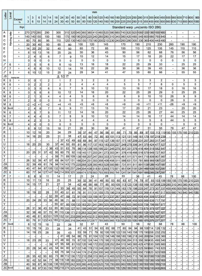
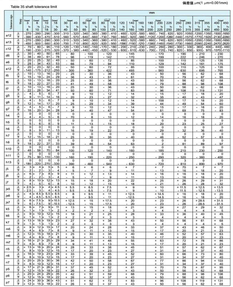
             THE ESTABLISHMENT OF THE TOLERANCE RANGE
               (as per ISO basic deviation and ISO standard tolerance)
                    Table 31 and 33 show the basic deviation value, i.e. the plus or minus deviation values
                (the minimum space) closest to the zero line.
                 Another deviation can be got through plus or minus the basic tolerances (T) in table 32.
|
|
Ao -- |
Ao
--Upper deviation |
|
Au -- |
Au --Lower deviation |
|
|
T
-- |
T
--Basic tolerance;T=Ao-Au |
|
|
G -- |
G --Basic deviation (minimum
space from zero line) |
|
|
Tolerance range
for the shaft and the hole |
||

                    Example:
                    the determination of the deviation value for the following tolerance sizes.
|
|
125H6 |
||
|
Ao = G = -20μm(见表31) T = 21μm(见表32) Au =-20-21=-41μm |
Au = G = 0(见表33) T = 25μm(见表32) Ao =0+25=+25μm |
||
|
因此: |
-0.020 |
因此:125H6=125 |
+0.025 |
|
-0.041 |
0 |
||
|
|
|
||
|
60js5 |
250R7 |
|
|
T = 13μm(见表32) Ao =+6.5μm Au = -6.5μm 因此:60js5=60±0.0065 |
Ao = G = -67μm(见表33) T = 46μm(见表32) Au =-67-46=-113μm |
|
|
因此:250R7=250 |
-0.067 |
|
|
-0.113 |
||
|
|
|
|